Chevrolet Equinox Service Manual: Intermediate Steering Shaft Replacement Steering Wheel and Column

Caution:With wheels of the vehicle facing straight ahead, secure the steering wheel utilizingsteering column anti-rotation pin, steering column lock, or a strap to prevent rotation.Locking of the steering column will prevent damage and a possible malfunction of theSIR system. The steering wheel must be secured in position before disconnecting thefollowing components: The steering columnThe intermediate shaft(s)The steering gearAfter disconnecting these components, do not rotate the steering wheel or move thefront tires and wheels. Failure to follow this procedure may cause the SIR coil assemblyto become un-centered and cause possible damage to the SIR coil. If you think theSIR coil has become un-centered, refer to your specific SIR coil’s centering procedureto re-center SIR Coil. Preliminary ProcedureWith the front wheels in the straight ahead position, turn the ignition switch tothe OFF position and remove the key from the ignition lock cylinder.Rotate the steering wheel in order to lock the steering column.Remove the left side instrument panel insulator panel. Refer toInstrument Panel Insulator Panel Replacement - Left Side.Use paint in order to place match marks on the steering column shaft and on the intermediatesteering shaft.Raise and support the vehicle. Refer toLifting and Jacking the Vehicle.Use paint in order to place match marks on the intermediate steering shaft and onthe steering gear pinion shaft. | |
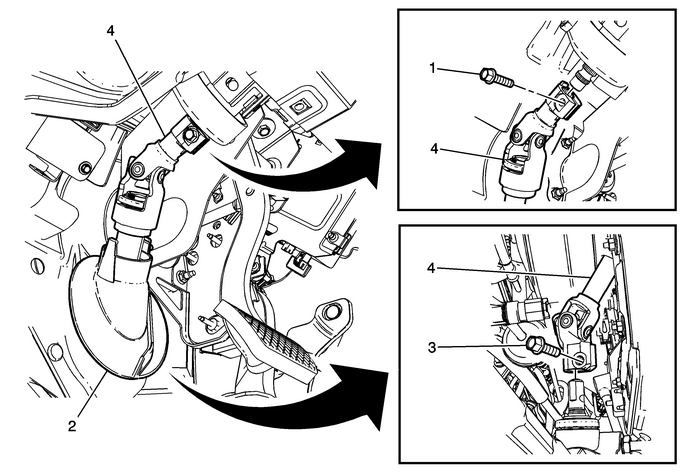
1 | Intermediate Steering Shaft Upper Bolt Caution:Refer toFastener Caution. ProcedureRemove the intermediate steering shaft upper bolt.Discard the bolt. Install a NEW intermediate steering shaft upper bolt.Tip:A NEW intermediate steering shaft upper bolt has a thread locking adhesive patch onthe threads. Tighten34-Y (25-lb-ft) |
2 | Intermediate Steering Shaft Seal Procedure If you are replacing the intermediate steering shaft, disengage the seal from thefloor and slide the seal up the intermediate steering shaft. Tip:The intermediate steering shaft seal is for a single use only. If you are NOT replacingthe intermediate steering shaft, DO NOT disengage the seal from the floor. |
3 | Intermediate Steering Shaft Lower Bolt ProcedureFrom the left front wheelhouse opening, remove the intermediate steering shaft lowerbolt.Discard the bolt. Install a NEW intermediate steering shaft lower bolt.Tip:A NEW intermediate steering shaft lower bolt has a thread locking adhesive patch onthe threads. Tighten34-Y (25-lb-ft) |
4 | Intermediate Steering Shaft ProcedurePull the intermediate steering shaft off of the steering column shaft.Pull the intermediate steering shaft off of the steering gear pinion shaft in an axialdirection.If you are replacing the intermediate steering shaft, copy the match marks from theold intermediate steering shaft to the new intermediate steering shaft.Align the match marks and connect the intermediate steering shaft to the steeringgear pinion shaft in an axial direction.Align the match marks and connect the intermediate steering shaft to the steeringcolumn shaft.Push the intermediate steering shaft in an axial direction onto the steering gearpinion shaft shoulder.After installation, center the steering angle sensor. Refer toSteering Angle Sensor Centering. |
 Steering Column Accident Damage Inspection Steering Wheel and Column
Inspection ProcedureRemove the turn signal switch bracket. Refer toTurn Signal Switch Bracket Replacement.Caution:Vehicles involved in accidents that result in any of thefollowing kinds of damage or s ...
 Power Steering System Description and Operation (Electronic Power Steering) Hydraulic Steering
K43Power Steering Control ModuleK17Electronic Brake Control ModuleP16Instrument ClusterB137Power Steering Shaft Torque SensorM38Power Steering MotorThe power steering system consists of the following ...
Other materials:
OnStar Overview
Voice Command Button
Blue OnStar Button
Red Emergency Button
This vehicle may be equipped with a
comprehensive, in-vehicle system
that can connect to an OnStar
Advisor for Emergency, Security,
Navigation, Connections, and
Diagnostics Services. OnStar
services may require a paid
subs ...
