Chevrolet Equinox Service Manual: Fuel Feed Intermediate Pipe Replacement Engine Control
Chevrolet Equinox Service Manual / Powertrain / Internal Combustion Powertrain Control / Fuel Feed Intermediate Pipe Replacement Engine Control

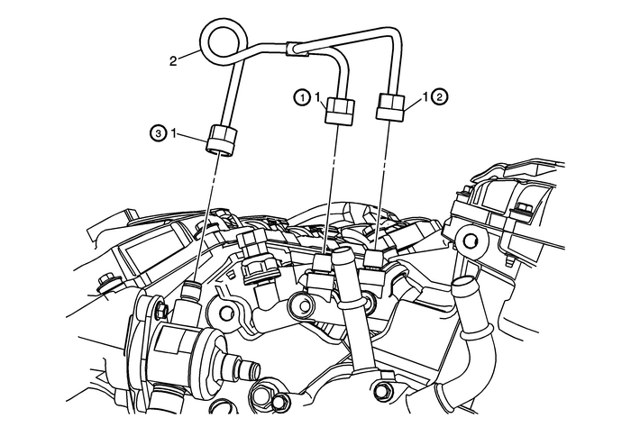
| Preliminary ProceduresRelieve the fuel system pressure. Refer toFuel Pressure Relief.Remove the Intake manifold cover. Refer toIntake Manifold Cover Replacement.Remove the fuel pipe shield. Refer toFuel Pipe Shield Replacement. | |
1 | Fitting (Qty: 3) Caution:Refer toFastener Caution. TightenTighten the fittings in sequence (1, 2, 3).First Pass15-Y(11-lb-ft)Second Pass30-Y(22-lb-ft) |
2 | Fuel Feed Intermediate Pipe ProcedureDiscard the pipe when removed and install a NEW pipe.Lubricate the pipes with silicon free engine oil. Refer toAdhesives, Fluids, Lubricants, and Sealers.Pressure up the fuel system and check for leaks. |
 Fuel Feed Hose Replacement Engine Control
Fuel Feed Hose ReplacementCalloutComponent NamePreliminary ProceduresRelieve the fuel system pressure. Refer toFuel Pressure Relief.Raise and support the vehicle. Refer toLifting and Jacking the Vehic ...
 Fuel Feed Intermediate Pipe Replacement Engine Control
Fuel Feed Intermediate Pipe ReplacementCalloutComponent NamePreliminary ProceduresRelieve the system pressure. Refer toFuel Pressure Relief.Remove the fuel pump cover. Refer toFuel Pump Cover Replacem ...
Other materials:
Front Seat Back Cushion Finish Panel Replacement Seats Front
Front Seat Back Cushion Finish Panel ReplacementCalloutComponent Name1Driver or Passenger Seat Back Cushion Finish PanelProcedurePull the panel rearward at the bottom edge first to disengagethe lower retainers.Move the finish panel and side clips to one side to disengagethe panel from the seat frame ...
© 2017-2026 Copyright www.cequinox.com

