Chevrolet Equinox Service Manual: Drivetrain and Front Suspension Frame Replacement
Special Tools
DW-110-060 Engine Assembly Support Fixture
Removal Procedure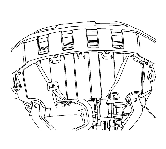
Support the powertrain using the support fixture. This fixture is used to keep thepowertrain from rocking fore/aft once the front and rear mounts are disconnected.Refer toEngine Support Fixturefor the 2.2L or 2.4L engine orEngine Support Fixturefor the 2.8L, 3.0L, 3.2L or 3.6L engine.Remove the front wheels. Refer toTire and Wheel Removal and Installation.Disconnect the front control arm ball joint from the knuckle. Refer toLower Control Arm Ball Joint Replacement.Remove the front exhaust pipe assembly. Refer toCatalytic Converter Replacementfor the 2.2L or 2.4L engine orExhaust Flexible Pipe Replacementfor the 2.8L, 3.0L, 3.2L or 3.6L engine.Remove the propeller shaft, if equipped. Refer toPropeller Shaft Replacement.
Note:Do not allow the radiator to swing after removing the front suspension crossmember.
Secure the upper part of the radiator with mechanics wire.Disconnect the 2 stabilizer shaft links from the struts. Refer toStabilizer Shaft Link Replacement.If equipped with hydraulic power steering, remove the steering gear to front suspensioncrossmember bolts.If equipped with rack electronic power steering, disconnect the electrical connectorsand remove the steering gear with the drivetrain and front suspension frame. RefertoSteering Gear Replacement.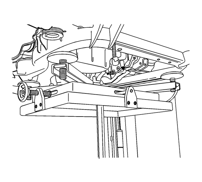
Support the front suspension crossmember by a jack stand.Remove the front suspension crossmember to transmission rear mount bracket bolts.
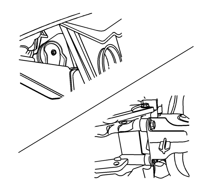
Remove the transmission front mount to front suspension crossmember bolt and disconnectthe mount from the frame.
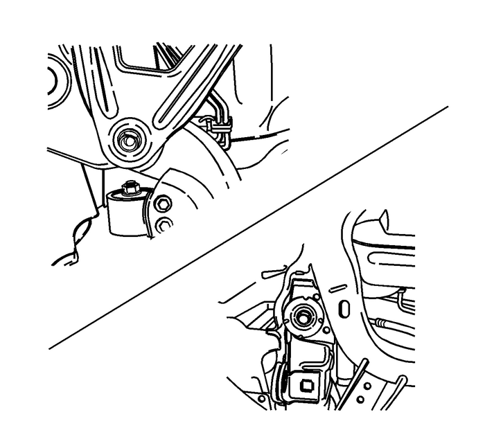
Remove the front suspension crossmember to body bolts.
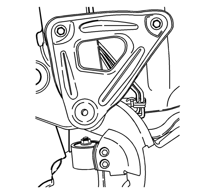
Remove the front suspension crossmember support bracket to body bolts.Lower the front suspension crossmember slowly with care. Rotate the stabilizer shaftproperly in order to have enough space.Remove the stabilizer shaft. Refer toStabilizer Shaft Replacement.Remove the 2 control arms. Refer toLower Control Arm Replacement.Installation ProcedureInstall the 2 front control arms. Refer toLower Control Arm Replacement.Install the stabilizer shaft. Refer toStabilizer Shaft Replacement.

Raise the front suspension crossmember slowly with care using a jack stand. Rotatethe stabilizer shaft properly in order to settle the front suspension crossmemberin the correct position.If equipped with rack electronic power steering, install the steering gear. RefertoSteering Gear Replacement.
Caution:Refer toFastener Caution.
Install the front suspension crossmember support bracket and front suspension crossmemberto body bolts.Tighten the front suspension crossmember to body bolts to 155-Y (114-lb-ft).Tighten the front suspension crossmember support bracket to body bolts to 58-Y (43-lb-ft).Install the front suspension crossmember to transmission rear mount bolts and tightento 110-Y (81-lb-ft).
Install the transmission front mount to transmission bolts and tighten to 50-Y (37-lb-ft).Install the front suspension crossmember to transmission front mount bolt and tightento 110-Y (81-lb-ft).Install the transmission rear mount to transmission bolts and tighten to 50-Y (37-lb-ft).Install the front suspension crossmember to transmission rear mount through bolt andtighten to 110-Y (81-lb-ft).

If equipped with hydraulic power steering, install the power steering gear to frontsuspension crossmember bolts and tighten to 110-Y (81-lb-ft).Connect the 2 stabilizer shaft links to the struts. Refer toStabilizer Shaft Link Replacement.
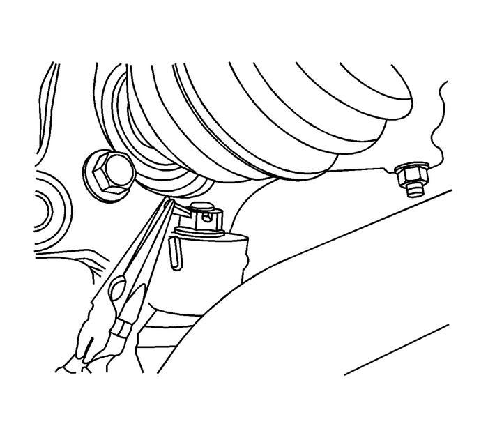
Install the front exhaust pipe assembly. Refer toCatalytic Converter Replacementfor the 2.2L or 2.4L engine orExhaust Flexible Pipe Replacementfor the 2.8L, 3.0L, 3.2L or 3.6L engine.Connect the front control arm ball joint to the knuckle. Refer toLower Control Arm Replacement.Install the front wheels. Refer toTire and Wheel Removal and Installation.Remove the engine support fixture. Refer toEngine Support Fixturefor the 2.2L or 2.4L engine orEngine Support Fixturefor the 2.8L, 3.0L, 3.2L or 3.6L engine.Measure and adjust the front toe. Refer toWheel Alignment - Steering Wheel Angle and/or Front Toe Adjustment.
 Drivetrain and Front Suspension Frame Insulator Replacement
Special Tools CH-47672-A Frame Insulator Remover/InstallerFor equivalent regional tools, refer toSpecial Tools.Removal ProcedureRemove the frame from the vehicle. Refer toDrivetrain and Front Suspensi ...
 Knuckle Replacement Knuckles
Special Tools J 37043 Park Brake Cable Release ToolRemoval ProcedureRaise and support the vehicle. Refer toLifting and Jacking the Vehicle.Remove the tire and wheel. Refer toTire and Wheel Removal and ...
Other materials:
Starting the Vehicle with a Low Transmitter Battery
When the vehicle is started, if the
transmitter battery is weak, the DIC
may display NO REMOTE
DETECTED or NO REMOTE KEY
WAS DETECTED PLACE KEY IN
TRANSMITTER POCKET THEN
START YOUR VEHICLE. The
REPLACE BATTERY IN REMOTE
KEY message may also be
displayed at this time.
To start the vehicl ...
