Chevrolet Equinox Service Manual: Driveline Working Angles Measurement
Special ToolsJ-23498-ADriveshaft Inclinometer, or equivalentJ-23498-20Driveshaft Inclinometer Adapter, or equivalent
Note:This measurement procedure is intended to measure U-jointsworking angles only, not constant velocity (CV) joint or couplerassembly working angles.
Note:This procedure is intended to be used for vehicles where thefollowing conditions are met:
Vehicle trim heights are within specificationguidelines.The vehicle exhibits no signs of aftermarket modificationsthat may affect driveline working angles.The vehicle exhibits no signs of accident damage which mayaffect the position of the drive axle, or axles, the propellershaft support bearing, if equipped, or the transmission or transfercase, if equipped.
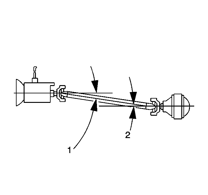
The working angle of a U-joint is formed by the differencebetween the angles of any 2-shafts that intersect.Propeller shaft systems that have 1-U-joint have1-working angle; systems with 2-U-joints have2-working angles, and so on. In a typical 1-piece propsystem with 2-U-joints, the working angles arefront-(1) and rear-(2):
The front working angle-(1) is formed by theintersection of the transmission or transfer case output shaft andthe prop shaft.The rear working angle-(2) is formed by theintersection of the prop shaft and the drive axle pinion.Note:When measuring and evaluating U-joint working angles, observethe following:
No U-joint working angle should be equal to zero. An angle of0-degrees will cause premature U-joint wear due to alack of rotation of the needle bearings in the U-joint.No U-joint working angle should exceed4-degrees.Prop systems containing only 1-U-joint: TheU-joint working angle should be within the range specified in thisprocedure.Prop systems containing 2-or3-U-joints: The 2-U-joint angles each formedwith the prop shaft that contains 2-welded yokes aredesigned to cancel each other during operation. These2-working, or cancelling U-joint angles should be equalto each other within the range specified in this procedure provideeffective cancellation of the U-joints.Prop systems containing 3-U-joints: The U-jointangle formed by the prop shaft that contains only1-welded yoke is an odd, or non-cancelled angle. Thisworking angle should be within the range specified in thisprocedure.Always orientate theJ-23498-ADriveshaft Inclinometer, or equivalent so that it faces the same side of thevehicle for each measurement taken.
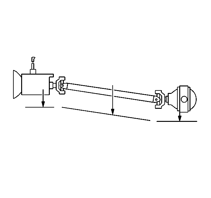
Be sure to accurately record the measurements taken on adiagram, similar to the one shown.Measurement Procedure
Note:If it is necessary to use theJ-23498-20Driveshaft Inclinometer Adapter, or equivalent adapter, first verify the accuracy of theJ-23498-20Driveshaft Inclinometer Adapter, or equivalent by inspecting the angle of an accessiblejoint using theJ-23498-ADriveshaft Inclinometer, or equivalent, then inspecting the same joint angleusing theJ-23498-20Driveshaft Inclinometer Adapter, or equivalent.
For vehicles with solid axles, ensure that the vehicle has afull tank of fuel or the equivalent amount of weight in the correctlocation to simulate a full tank. The weight of 3.8-L(1-gal) of gasoline is approximately 2.8-kg(6.2-lb).Raise and support the vehicle. On vehicles with solid axles,ensure that the drive axle is supported at rideheight—vehicle body supported by suspension components.Suspension travel will not affect driveline angles on vehicles withdirect-mounted drive axles. Ensure the wheels are free to rotate.Refer toLifting and Jacking the Vehicle.For vehicles with 2-piece prop shaft systems, inspect thelateral alignment of the propeller shafts before proceeding:From underneath the propeller shafts, look down the length ofthe shafts from front to rear. Inspect the alignment of the shaftsto each other.From underneath the shafts, if the propeller shafts are notaligned to each other in a straight line, then the lateralalignment of the prop shafts needs to be adjusted beforeproceeding.The propeller shaft support bearing assembly can be relocatedslightly to one side in order to improve the alignment of theshafts. Ensure that you do not create a ground-out conditionagainst the exhaust or any other component.
Place the transmission in NEUTRAL.Clean any corrosion or foreign material from the U-jointbearing caps.Remove any of the U-joint bearing cap snap rings that mayinterfere with the correct placement of theJ-23498-ADriveshaft Inclinometer, or equivalent .
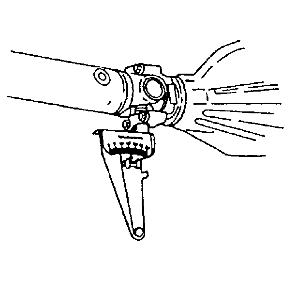
For all prop systems perform the first measurement:Rotate the prop shaft to align the rear-most yoke flangesvertically.Install theJ-23498-ADriveshaft Inclinometer, or equivalent to the lower U-joint bearing cap of therear-most yoke. This yoke may be part of a prop shaft, torque tubeinput shaft, or a drive axle pinion shaft. Measure and record theangle of the shaft.For prop systems with 2-or 3-U-joints,perform this additional measurement:
Without rotating the prop, install theJ-23498-ADriveshaft Inclinometer, or equivalent to the lower U-joint bearing cap of theforward-most, vertically-aligned yoke. This yoke may be part of aprop shaft, transmission output shaft, or a transfer case outputshaft. Measure and record the angle of the shaft.
For all prop systems perform the second measurement:Rotate the prop shaft 1/4-turn to vertically alignthe flanges of the forward yoke that mates to the rear-mostyoke.Install theJ-23498-ADriveshaft Inclinometer, or equivalent to the lower U-joint bearing cap of theforward mating yoke. This yoke may be part of a prop shaft,transmission output shaft, or a transfer case output shaft. Measureand record the angle of the shaft.For prop systems with 3-U-joints, perform thisadditional measurement:Without rotating the prop, install theJ-23498-ADriveshaft Inclinometer, or equivalent to the lower U-joint bearing cap of theforward-most, vertically-aligned yoke. This yoke may be part of atransmission output shaft, or a transfer case output shaft. Measureand record the angle of the shaft.
Remove theJ-23498-ADriveshaft Inclinometer, or equivalent .Install any U-joint bearing cap snap rings that were removedprior to installing theJ-23498-ADriveshaft Inclinometer, or equivalent .Calculate the U-joint working angle at each intersection oftwo shafts.Subtract the smaller number from the larger to obtain theworking angle. For example: If the drive axle pinion has an angleof 16-degrees and the connecting propeller shaft has anangle of 13-degrees, then the working angle of thatintersection is 3-degrees.
For prop systems with 1-U-joint; compare theworking angle to the following specification guideline:Specification Guideline
Prop systems containing only 1-U-joint: TheU-joint working angle should be between 1/2-and3/4-degrees.For prop systems with 2-or 3-U-joints;compare the difference between the working angles of the cancellingU-joints to the following specification guidelines:
Specification Guideline
Allowable range of difference between cancelling U-jointworking angles: 0.25-to 1.0-degreesFor prop systems with 3-U-joints; compare theworking angle of the odd, or non-cancelled U-joint to the followingspecification guideline:
Specification Guideline
Prop systems containing 3-U-joints: The odd, ornon-cancelled U-joint working angle should be between1/10-and 1/2-degrees.Any working angle that is not within the specificationguidelines requires adjustment.
 Rear Axle Shaft Seal Replacement - Right Side Driveshafts Drive Halfshafts
Special ToolsJ-44809Seal InstallerRemoval ProcedureRaise and support the vehicle. Refer toLifting and Jacking the Vehicle.Drain the rear differential. Refer toDifferential Oil Replacement.Remove the e ...
 Propeller Shaft Phasing Inspection Driveshafts Propeller Shaft Assembly
Special ToolsJ-23498-ADriveshaft Inclinometer, or equivalentNote:This inspection procedure is intended to inspect propellershaft systems with 2-or 3-U-jointsonly.Correct phasing of a propeller shaft r ...
Other materials:
General Plastic Repair
Warning:In order to reduce the risk of personal injury when exposedto toxic fumes while grinding, cutting, or applying repair materialon any type of sheet molded compound or RIM rigid plastic, observethe following guidelines:Work in a properly ventilated areaApply protective cream to any exposed ski ...
