Chevrolet Equinox Service Manual: Drive Range, First Gear Engine Braking Automatic Transmission Unit
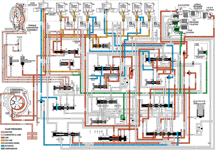
When the gear selector lever is moved to the Drive-(D) range from the Neutral-(N)position, the transmission will provide engine braking. In this operating range, thenormally-low 1234-pressure control solenoid-5 is commanded ON and in the engine brakingmode the following changes occur within the hydraulic circuits:
Fluid Pressure is Directed to the 1-2-3-4 Clutch and the Low & Reverse Clutch to ProvideEngine BrakingManual Valve
The manual valve is moved to the Drive-(D) position and allows line fluid pressureto enter the drive fluid circuit. Drive fluid is then routed to the clutch selectvalve-2.
Clutch Select Valve 2
Drive fluid at the clutch select valve-2 passes through the valve and enters the drivebrake circuit. Drive brake fluid is then routed to the clutch select valve-3.
Clutch Select Valve 3
Drive brake fluid at the clutch select valve-3 passes through the valve and entersthe Drive B fluid circuit. Drive B fluid is then routed to #1-ball check valve.
#1 Ball Check Valve
Drive B fluid seats the #1-ball check valve against drive-1-6 fluid to force drive-Bfluid into the 26/1234 feed passage. The 26/ 1234 feed fluid is routed through orifice-#31and, to the 2-6-clutch regulator valve. The 26/1234 feed fluid passes through the2-6-clutch regulator valve and enters the pressure switch-3-(PS3) fluid circuit. PS3fluid is then routed to the normally closedpressure switch-3 and opens the switch.
#6 Ball Check Valve
26/1234 feed fluid unseats the #6-ball check valve allowing 26/1234 feed fluid toenter the 1234 clutch feed circuit. The 1234-clutch feed fluid is routed through orifice-#25and then to the 1-2-3-4-clutch regulator valve.
1-2-3-4 Clutch Applies1234 Pressure Control Solenoid 5
The 1234 pressure control solenoid-5 is commanded ON allowing actuator feed limitto enter the PCS-1234 clutch fluid circuit. PCS-1234 clutch fluid is then routed throughtorifice- #27 to the 1-2-3-4-clutch regulator valve. PCS1234-clutch fluid is also routedthrough orifice-#29 and then to the 1-2-3-4-clutch boost valve.
1-2-3-4 Clutch Regulator Valve
PCS1234-clutch fluid moves the 1-2-3-4-clutch regulator valve against 1-2-3-4-clutchregulator valve spring force to allow 1234-clutch feed fluid to pass through the valveand enter the 1234-clutch fluid circuit. The 1234-clutch fluid is then routed to the1234-clutch boost valve and the 1-2-3-4-clutch.
1-2-3-4 Clutch Boost Valve
PCS1234-clutch fluid pressure acts on a differential area moving the 1234-clutch boostvalve against the 1234-clutch boost valve spring. The 1234-clutch fluid passes throughthe valve and enters the 1234- clutch feedback circuit. As PCS 1234-clutch fluid pressureis increased to a given value, the 1234-clutch boost valve opens the 1234-clutch feedbackcircuit to exhaust. This resultsin the 1234-clutch regulator valve moving to the full feed position sending full 26-CL/1234CL feed pressure (full line pressure) to the clutch.
1-2-3-4 Clutch
The 1234-clutch fluid enters the 1234-clutch to move the piston against spring forceto apply the 1-2-3-4-clutch plates.
Drive Range, First Gear Engine Braking
 Park - Engine Running (Gen 2/Hybrid) Automatic Transmission Unit
When the gear selector lever is in the Park (P) position,fluid is drawn into the pump through the transmission fluid filterassembly. Line pressure is then directed to the followingvalves:Fluid Pressur ...
 Reverse Automatic Transmission Unit
When the gear selector lever is moved to the Reverse (R) position (from the Park position)the normally high 35R pressure control solenoid 2 is commanded ON and the followingchanges occur in the transm ...
Other materials:
Timing Chain Idler Sprocket Replacement - Right Side Valvetrain Valvetrain Timing Timing Belt/Chain
Removal ProcedureRemove the engine front cover. Refer toEngine Front Cover Replacement.Remove the spark plugs in order to ease crankshaft/enginerotation. Refer toSpark Plug Replacement.Remove the right bank secondary camshaft drive chaintensioner. Refer toSecondary Timing Chain Tensioner Removal - R ...
